Executing a mechanical road trip vehicle checklist seven days before departure verifies four load-bearing and thermal subsystems: cold tire inflation and tread depth under 49 CFR §571.110 and 49 CFR §571.138, engine oil and pressurized ASTM D3306 50/50 glycol coolant margins, hygroscopic brake fluid boiling thresholds under 49 CFR §571.116 alongside inboard/outboard brake pad friction thickness, and 12V battery open-circuit voltage (12.60–12.80 V) plus loaded alternator output (13.8–14.5 V). Skipping these quantitative measurements leaves a loaded highway vehicle vulnerable to unwarned 15–20% tire underinflation, +87-foot wet-braking penalties at 60 mph, cooling-system boil-over on summer grades, caliper brake-fluid vapor lock on mountain descents, or a no-start 12V battery failure hundreds of miles from home.
While our three-stage road trip checklist for car prep, packing, and stops maps out the broader departure timeline and our daily driving distance and fatigue guide establishes safe hours behind the wheel, this technical inspection guide details the exact under-hood and undercarriage engineering thresholds, measurement conditions, and pass/fix gates for gas, hybrid, and electric passenger vehicles.
| Subsystem & Inspection Item | Governing Standard / Reference | Pre-Trip Pass Threshold (“Go”) | Caution / Service Gate (“Fix First”) | Dominant Highway Failure Mode |
|---|---|---|---|---|
| Cold Tire Inflation Pressure | 49 CFR §571.110 (FMVSS 110 B-pillar placard); NHTSA Tires | Set cold (≥ 3 hr parked or < 1 mi driven) to exact B-pillar placard spec (30–36 psi typical); ~1 psi / 10 °F shift |
Any tire > 2–3 psi below placard cold; TPMS telltale only required at -25% (49 CFR §571.138) |
Excessive sidewall flex, carcass heat buildup, tread separation, and degraded wet lane-change stability |
| Tire Tread Depth (All 3 Grooves) | 49 CFR §571.139 (2/32 in. TWI); USTMA & AAA wet-braking data |
≥ 4/32 in. (3.2 mm, quarter test) for wet highway; ≥ 6/32 in. (4.8 mm) for snow/alpine passes |
< 4/32 in. for wet multi-day routes; ≤ 2/32 in. (1.6 mm, penny test) is legal condemnation limit |
Hydroplaning in standing highway water; +87 ft (+43%) longer wet stop from 60 mph at 2/32 in. |
| Tire DOT Age & Compact Spare | 49 CFR §574.5 (WWYY TIN); NHTSA |
< 6 years from WWYY DOT stamp; T-type compact spare inflated to 60 psi (415 kPa) cold |
6–10 years (inspect for ozone cracking / replace per OEM); > 10 years mandatory replacement |
Thermo-oxidative belt-edge delamination at highway speed; flat 25 psi trunk spare unusable on shoulder |
| Engine Oil Level & Service Life | API SP / ILSAC GF-6; NHTSA Summer Driving Tips |
Film between MIN and MAX dipstick marks; ≥ 20–25% oil life remaining for 1,500–3,000 mi trip |
Level at/below MIN (~1.0 qt low) or < 20% Oil Life Monitor / due within 1,500 mi |
High-RPM thermal oxidation (220–250 °F sump), viscosity shear, and timing-chain/bearing wear |
Engine Coolant (50/50 Glycol) |
ASTM D3306 (OAT / HOAT / P-OAT) under 15 psi (103 kPa) cap |
Cold reservoir at FULL COLD; 50/50 mix (-34 °F freeze, ~265 °F boil at 15 psi); firm EPDM hoses |
Freeze point > -20 °F, leaking pressure cap (223 °F boil at 0 psig), or spongy EPDM hose ends |
Flash boil-over on steep mountain grades; internal hose Electrochemical Degradation (ECD) rupture |
Brake Fluid Boiling Point (ERBP) |
49 CFR §571.116 (FMVSS No. 116) | Moisture < 1.5% H₂O; Dry ERBP ≥ 401 °F (DOT 3) or ≥ 446 °F (DOT 4) |
2.0–2.5% H₂O (caution); ≥ 3.0–3.5% H₂O drops DOT 3 boiling point to 284 °F (140 °C) — flush first |
Compressible steam bubble formation (vapor lock) inside hot calipers on downhill grades; pedal drops to floor |
Brake Pad Lining & Rotor DTV |
OEM caliper inspection & rotor micrometer spec | ≥ 4–5 mm (~3/16 in.) friction material on inboard & outboard pads; smooth braking from 70 mph |
< 4 mm before mountain/loaded trips; ≤ 2–3 mm (2/32–3/32 in.) wear-tab chirp or DTV > 12–25 µm |
Rapid heat conduction through thin backing plate into fluid; backing-plate rotor scoring; steering shake |
12V Battery (SOC/SOH) & Alternator |
SAE J537 Cold Cranking Amps (CCA) & multimeter test |
Resting OCV 12.60–12.80 V (100% SOC); cranking ≥ 9.6 V; alternator 13.8–14.5 V under load |
Resting OCV ≤ 12.40 V (≤ 75% SOC sulfation), < 75–80% rated CCA, or alternator < 13.5 V / > 14.8 V |
Heat-soaked highway rest-stop no-start; hybrid/EV high-voltage contactor lockout if 12V auxiliary rail sags |
1. Tire Pre-Departure Audit: Cold Inflation Physics, TPMS Blind Spots, Tread Depth, and DOT Age
Tires carry the entire static curb weight, passenger payload, and roof-box aerodynamic downforce while generating every traction vector for braking and evasive steering. A complete road trip checklist for car tires requires four distinct checks: cold inflation pressure against the door-jamb placard, tread depth across all three circumferential grooves, sidewall DOT manufacture date decoding, and compact spare or sealant-kit verification.
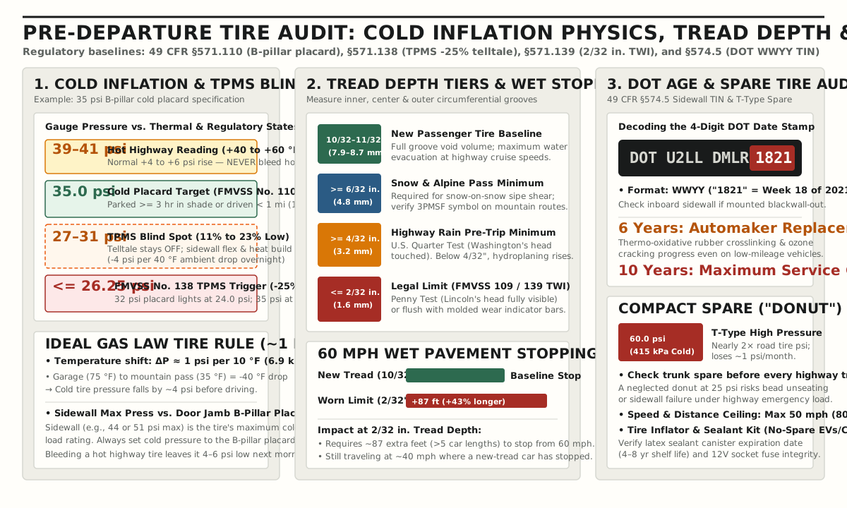
Cold Placard Target (FMVSS No. 110) vs. Highway Thermal Rise (~1 psi / 10 °F)
Under 49 CFR §571.110 (FMVSS No. 110), every passenger vehicle sold in the United States carries a permanent Tire and Loading Information placard affixed to the driver’s door B-pillar (door jamb). This placard specifies the vehicle’s maximum combined occupant and cargo weight capacity and the recommended cold tire inflation pressure for front, rear, and spare tires—typically 30 to 36 psi (207 to 248 kPa) for passenger sedans and crossovers.
Per NHTSA tire safety guidance, “cold” inflation pressure means measuring the tire when the vehicle has been parked for at least 3 hours (out of direct sunlight, which radiatively heats the sun-facing tires) or driven less than 1 mile (1.6 km) at moderate speed. Two physical errors routinely compromise pre-trip tire adjustments:
- Confusing the Sidewall Maximum with the B-Pillar Target: The pressure molded into the tire sidewall (for example,
MAX PRESS 44 PSIor51 PSI) designates the maximum cold pressure the tire carcass is rated to hold at its maximum load index. Inflating a32 psiplacard vehicle to44 psishrinks the tire contact patch center, accelerates center-rib wear, harshness, and braking distance on dry rough pavement. Conversely, using the B-pillar placard matches the tire’s vertical spring rate and footprint to the vehicle’s suspension geometry. - Bleeding Air from Hot Tires at Highway Rest Stops: By Gay-Lussac’s ideal gas law (
P₁ / T₁ = P₂ / T₂in absolute temperature), sealed tire gauge pressure changes by approximately1 psifor every10 °F(6.9 kPaper5.6 °C) change in internal air temperature. Sustained highway driving at65 to 75 mphflexes the viscoelastic rubber sidewall and tread belt, warming internal air by40 to 60 °Fand raising gauge pressure by+4 to +6 psiabove the cold placard setting. Never bleed air from a hot tire at a fuel stop to bring the gauge back down to the cold placard figure: once the tire cools overnight, it will sit4 to 6 psiunderinflated.
Why the FMVSS No. 138 TPMS Light Stays Dark Until -25% Underinflation
Relying on the dashboard Tire Pressure Monitoring System (TPMS) icon instead of a calibrated dial or digital gauge leaves a wide unwarned margin. Under 49 CFR §571.138 (FMVSS No. 138), an automotive TPMS telltale is only required to illuminate within 20 minutes when inflation pressure in one or more tires drops 25% or more below the automaker’s recommended cold placard pressure (or to the minimum activation pressure table, 20 psi for P-metric standard-load tires, whichever is higher).
Conditional Calculation Example: Cold Thermal Drop & TPMS Threshold Math
Consider a loaded crossover carrying four passengers and luggage (P_placard = 35.0 psi cold on the B-pillar placard). Under 49 CFR §571.138, the federal low-pressure warning threshold (P_tpms) is:
P_tpms = 35.0 psi × (1 − 0.25) = 26.25 psi(on a32.0 psiplacard sedan,P_tpms = 32.0 × 0.75 = 24.0 psi).- Suppose the driver checks the tires immediately after a
70 mphhighway warm-up run where internal air temperature rose from65 °Fambient to115 °F(ΔT = +50 °F, adding≈ +5 psithermal pressure), and the hot tire reads37.0 psi. - If the driver bleeds
2.0 psifrom the hot tire to match the35.0 psiplacard, the tire drops to35.0 − 5.0 = 30.0 psiwhen it cools back to65 °F. - If the vehicle then drives into high elevation and parks overnight at a
35 °Fmountain lodge (ΔT = −30 °Fambient drop, losing another≈ 3.0 psi), morning cold inflation pressure falls to27.0 psi.
At 27.0 psi, the tire is 8.0 psi (22.9%) underinflated for a fully loaded highway departure—increasing sidewall deflection, rolling resistance, fuel consumption, and belt-edge thermal stress—yet 27.0 psi still sits above the 26.25 psi federal FMVSS No. 138 telltale floor. Depending on the vehicle’s specific sensor hysteresis and temperature compensation, a manual cold gauge check is the only way to catch 10% to 23% underinflation before departure.
Tread Depth Tiers and 60 mph Wet Stopping Distance
Circumferential tread grooves channel standing water out from beneath the contact patch, while lateral sipes provide biting edges on wet or snow-packed pavement. As tread wears down, groove void volume shrinks and hydrodynamic water pressure lifts the tire off the asphalt (hydroplaning). Always measure tread depth in all three primary grooves (inboard, center, and outboard) to catch camber wear, toe feathering, or cupping:
| Tread Depth Tier | Measurement (in. / mm) |
Field Coin / Indicator Check | Highway Wet & Mountain Traction Performance |
|---|---|---|---|
| New Passenger Tire Baseline | 10/32 to 11/32 in. (7.9 to 8.7 mm) |
Depth gauge baseline | Full groove water-evacuation capacity at posted interstate speeds. |
| Snow & Mountain Route Minimum | 6/32 in. (4.8 mm) minimum |
Top of Lincoln Memorial on U.S. penny; USTMA winter guidance | Below 6/32 in., lug void volume and sipe depth lose snow-packing shear grip on alpine grades; verify 3PMSF symbol where traction laws apply. |
| Wet Highway Pre-Trip Minimum | 4/32 in. (3.2 mm) minimum |
U.S. Quarter Test: insert quarter upside down; if the top of Washington’s head is visible, < 4/32 in. remains |
AAA wet-pavement braking tests show measurable stopping distance growth at 4/32 in.; replace before multi-day rainy highway trips. |
Federal Legal Limit (FMVSS 139) |
2/32 in. (1.6 mm) |
U.S. Penny Test: top of Lincoln’s head fully visible, or flush with molded Tread Wear Indicator (TWI) bars |
AAA testing at 60 mph on wet pavement demonstrated +87 ft (+43%) longer stopping distance than new tires, with the car still moving at ~40 mph where a new-tread vehicle has stopped completely. |
Decoding 49 CFR §574.5 DOT Date Codes and the 60 psi Compact Spare Check
Even when a tire on a lightly driven second vehicle or garage cruiser shows 8/32 in. of remaining tread, the vulcanized rubber compound undergoes continuous thermo-oxidative crosslinking and antiozonant depletion when exposed to oxygen, heat, and UV light. Under 49 CFR §574.5, the complete Tire Identification Number (TIN) molded into the sidewall (check the inboard sidewall if the full code is not visible on the outboard side) ends with a 4-digit manufacture date stamp in WWYY format:
- First two digits (
WW): Week of manufacture (01through52/53). - Last two digits (
YY): Calendar year of manufacture (for example,1821= 18th week of 2021). - Service Age Gates: NHTSA notes that many vehicle manufacturers advise replacing tires at 6 years from manufacture regardless of tread depth, and industry guidelines set 10 years as the upper service ceiling—including unused spare tires stored in the trunk.
Before packing the trunk with luggage or loading the emergency roadside kit and cabin organizer, lift the cargo floor mat and test the spare tire:
- T-Type Compact Temporary Spares (“Donuts”): Require
60 psi(415 kPa) cold inflation pressure—nearly double road-tire pressure—and lose approximately1 psiper month via butyl permeation. A neglected spare sitting at25 psicannot safely carry highway emergency loads and is speed-limited to50 mph(80 km/h). - Tire Mobility / Sealant Kits (Many Hybrids and EVs): If the vehicle replaces a spare wheel with a 12V air compressor and liquid latex sealant cartridge, check the expiration date stamped on the sealant canister (typically
4 to 8 years) and confirm the 12V accessory socket fuse works.
2. Under-Hood Fluid Chemistry, Boiling Thresholds, and Thermal Margins
Highway road trips subject powertrain and braking fluids to sustained thermal loads that short urban commutes never reach. Climbing a long interstate grade at 70 mph in summer heat drives bulk engine oil sump temperatures to 220–250 °F (104–121 °C) and pushes cooling systems toward their pressure-regulated boiling ceiling, while descending the opposite side transfers megajoules of kinetic energy into the brake rotors and caliper fluid.
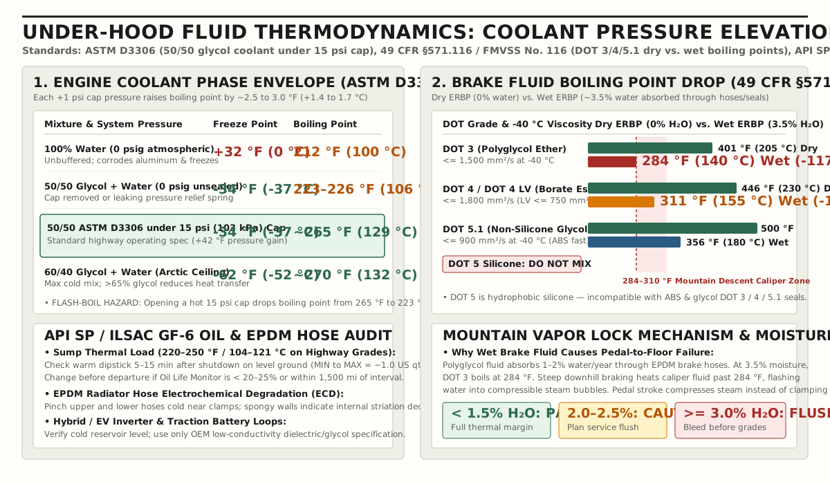
Engine Oil (API SP / ILSAC GF-6): Level Check and Highway Oxidation Margin
To check engine oil accurately on a wet-sump combustion or hybrid engine, park on level ground, bring the engine to normal operating temperature, shut it off, and wait 5 to 15 minutes so oil drains from the upper cylinder head galleries back into the oil pan (consult the owner’s manual for dry-sump or electronic-level-sensor engines). Pull the dipstick, wipe it clean with a lint-free cloth, reinsert it fully, and verify the oil film sits between the MIN/ADD and MAX/FULL crosshatch marks. That crosshatch span represents approximately 1.0 US quart (0.95 L).
- Top-Off Rule: Never overfill above the
MAXline; excess oil contacts the spinning crankshaft counterweights, whipping air bubbles into the lubricant (aeration/foaming) and collapsing oil pump pressure at the main bearings. - Pre-Trip Change Gate: Confirm the oil meets the manual’s exact viscosity grade (such as
SAE 0W-20or5W-30) andAPI SP/ILSAC GF-6specification. If a1,500 to 3,000 mileroad trip will consume the remaining margin on the vehicle’s Oil Life Monitor—or if remaining oil life sits below20% to 25%—change the oil and filter before leaving. Depleted anti-wear additives (ZDDP) and shear-thinned viscosity modifiers accelerate evaporative oil consumption (Noack volatility) during sustained3,000+ RPMmountain climbs.
Engine Coolant (ASTM D3306): 50/50 Glycol Freeze/Boil Physics and 15 psi Cap Elevation
Passenger car cooling systems rely on two mechanisms to prevent boil-over on steep summer grades and block-cracking freezes in alpine passes: colligative solute elevation (ASTM D3306 ethylene glycol or propylene glycol mixed with deionized water) and hydrostatic system pressurization via the spring-loaded radiator or expansion-tank cap.
| Coolant Mixture & System Pressure State | Freezing Point (°F / °C) |
Boiling Point (°F / °C) |
Engineering & Pre-Trip Inspection Notes |
|---|---|---|---|
100% Pure Water at 0 psig (14.7 psia sea level) |
+32 °F (0 °C) |
212 °F (100 °C) |
Zero freeze protection; lacks cavitation and aluminum/solder corrosion inhibitors; boils below 200 °F at 7,000 ft elevation. |
50/50 Ethylene Glycol + Water at 0 psig (Unpressurized) |
-34 °F (-37 °C) |
223–226 °F (106–108 °C) |
Unsealed boiling threshold when the radiator cap is open or its rubber pressure seal has cracked. |
50/50 ASTM D3306 Mix under 15 psi (103 kPa) Cap |
-34 °F (-37 °C) |
~265 °F (129 °C) |
Each +1 psi of cap pressure raises boiling point by ~2.5 to 3.0 °F (+1.4 to 1.7 °C), adding ~42 °F of boil-over protection. |
60/40 Ethylene Glycol + Water under 15 psi Cap |
-62 °F (-52 °C) |
~270 °F (132 °C) |
Cold-climate ceiling. Never exceed 65–70% glycol: freeze point reverses upward and specific heat capacity drops, hurting summer cooling. |
Critical Pre-Trip Cooling Checks:
- Never Open a Hot Pressurized Cap: Releasing a
15 psicap on a heat-soaked engine instantly drops the liquid’s boiling point from~265 °Fdown to223 °F, causing superheated coolant in the cylinder head to flash-boil explosively out the filler neck. Always inspect the translucent overflow or degas reservoir against theCOLD MINandCOLD MAXmarks with the engine cold. - EPDM Hose Electrochemical Degradation (
ECD) Test: With the engine cold, firmly pinch the upper and lowerEPDMrubber radiator hoses1 to 2 inchesfrom the metal hose clamps. Galvanic micro-currents flowing through aged coolant attack the inner rubber tube (ECD), creating internal longitudinal micro-fissures that make the hose feel spongy, soft, or crunchy from the inside out long before external surface cracks appear. - Hybrid and EV Inverter / Traction Battery Loops: Hybrid vehicles (see our analysis of hybrid highway and mountain grade behavior) and battery-electric vehicles carry dedicated low-conductivity cooling loops for the power-electronics inverter and high-voltage battery pack. Verify those reservoirs cold, and top off exclusively with the automaker’s specified dielectric or low-silicate/low-conductivity coolant.
Brake Fluid (49 CFR §571.116 / FMVSS No. 116): Hygroscopic Moisture Absorption and Mountain Vapor Lock
Glycol-ether brake fluids (DOT 3, DOT 4, and DOT 5.1) are intentionally hygroscopic—they absorb water molecules diffusing through microscopic pores in flexible EPDM brake hoses and master-cylinder seals at a rate of 1% to 2% water per year so free water droplets cannot pool and corrode steel brake lines or ABS modulator valves. However, dissolved water drastically lowers the fluid’s boiling point.
Under 49 CFR §571.116 (FMVSS No. 116), motor vehicle brake fluids are graded by two minimum boiling thresholds—Dry Equilibrium Reflux Boiling Point (Dry ERBP) (0% water content, fresh from a sealed container) and Wet ERBP (humidified reference sample containing approximately 3.5% to 3.7% water)—plus maximum kinematic viscosity at -40 °C (-40 °F) for cold-weather ABS/ESC valve response:
| FMVSS No. 116 Grade | Chemical Base | Minimum Dry ERBP (0% H₂O) |
Minimum Wet ERBP (~3.5% H₂O) |
Max Viscosity at -40 °C (mm²/s / cSt) |
Compatibility & Road-Trip Application |
|---|---|---|---|---|---|
DOT 3 |
Polyglycol ether (hygroscopic) | 401 °F (205 °C) |
284 °F (140 °C) |
≤ 1,500 mm²/s |
Common OEM fill on passenger sedans/crossovers; loses 117 °F (65 °C) of boiling margin when saturated at 3.5% moisture. |
DOT 4 / DOT 4 LV |
Polyglycol ether + borate esters (hygroscopic) | 446 °F (230 °C) |
311 °F (155 °C) |
≤ 1,800 mm²/s (DOT 4 LV Class 6 ≤ 750 mm²/s) |
Borate esters buffer moisture better at moderate water levels; specified for heavier crossovers, European platforms, and mountain routes. |
DOT 5.1 |
Polyglycol ether / borate ester (non-silicone, hygroscopic) | 500 °F (260 °C) |
356 °F (180 °C) |
≤ 900 mm²/s |
High thermal ceiling paired with low cold viscosity for fast ABS/ESC pulsing; miscible with DOT 3 and DOT 4. |
DOT 5 (Silicone — Do Not Mix) |
Polydimethylsiloxane silicone (hydrophobic) | 500 °F (260 °C) |
356 °F (180 °C) |
≤ 900 mm²/s |
Incompatible with DOT 3, DOT 4, DOT 5.1, and ABS systems. Entrains air micro-bubbles and lets free water pool and boil at 212 °F. |
Conditional Calculation Example: Cooling Cap Pressure vs. Downhill Brake Fluid Margin
To see why cooling-system pressurization and brake-fluid moisture act in opposite directions on a mountain pass:
- Uphill Climb (Pressurized Coolant): At
7,000 ftelevation, ambient atmospheric pressure drops pure water’s open boiling point to~199 °F. However, a sealed15 psiradiator cap maintains positive gauge pressure across the cooling loop:ΔT_boil ≈ 15 psi × 2.8 °F/psi = +42 °F, keeping a50/50ASTM D3306glycol mixture liquid up to~265 °F(129 °C). - Downhill Descent (Unpressurized Wet Brake Fluid): On the descent, a 3-year-old
DOT 3brake fluid that has absorbed3.5%moisture has lost401 °F − 284 °F = 117 °F(65 °C) of boiling margin under49 CFR §571.116. If repeated friction braking heats the front caliper pistons and fluid to295 °F(146 °C), the wetDOT 3fluid exceeds its284 °FWetERBPand flashes into compressible steam bubbles (vapor lock). Because gas is compressible while hydraulic liquid is not, pressing the brake pedal merely compresses the steam bubble inside the caliper bore instead of clamping the pads against the rotor. Under the identical295 °Fcaliper temperature, fresh dryDOT 4fluid (446 °FDryERBP) retains a151 °Fthermal safety buffer.
Pre-Trip Brake Fluid Action Gate: Wipe the master-cylinder reservoir cap clean before opening. Verify the level sits between MIN and MAX (note: a dropping fluid level without a visible leak normally reflects normal brake-pad wear as caliper pistons extend outward; do not top it off to MAX without inspecting pad thickness first). Test the fluid with an electronic moisture probe or test strip:
< 1.5% H₂O: Pass (Go).2.0% to 2.5% H₂O: Caution; schedule a flush before heavy towing or mountain travel.≥ 3.0% H₂O(or> 2–3 yearssince last flush): Flush and bleed the hydraulic system before departure.
Transmission, Driveline, and Windshield Washer Fluids
Complete the under-hood fluid sweep by checking automatic transmission fluid (ATF) or CVT fluid (if equipped with a dipstick, checked at the manual’s specified operating temperature and gear-selector sequence) for dark brown oxidation or burnt odor. Finally, fill the windshield washer reservoir with a dedicated surfactant bug-wash formula in summer or a -20 °F to -30 °F (-29 °C to -34 °C) methanol/glycol de-icer whenever routes cross high elevations or autumn freezes—never plain tap water, which freezes at 32 °F (0 °C), cracks the washer pump housing, and smears insect protein film across the glass.
3. Brake Friction Lining, Rotor Runout, and 12V Electrical Verification
A road trip vehicle checklist must look past fluid reservoirs to the friction surfaces that stop the car and the 12V electrical architecture that starts the engine and powers electronic safety systems.
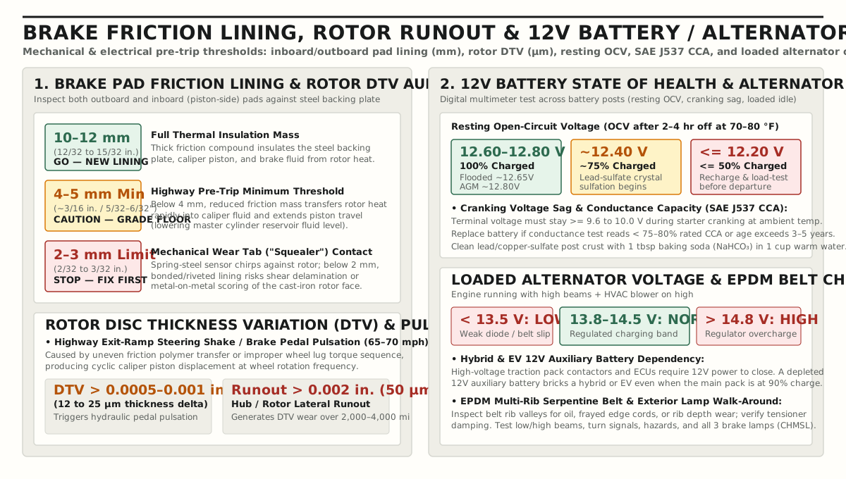
Brake Pad Friction Thickness (mm) and Rotor Disc Thickness Variation (DTV)
Sight through the wheel spokes with a flashlight (or remove a wheel during tire rotation) to measure the friction lining thickness—excluding the ~5 mm stamped steel backing plate—on both the outboard pad and the inboard (piston-side) pad, which frequently wears faster on single-piston sliding calipers if slide pins bind:
10 to 12 mm(12/32 to 15/32 in.) — New Pad Lining (Go): Provides full friction wear life and acts as a thick thermal insulator between the glowing cast-iron rotor and the metal caliper piston.4 to 5 mm(~3/16 in./5/32–6/32 in.) — Highway Pre-Trip Minimum (Caution / Replace for Grades): For flat interstate cruising,4 to 5 mmpasses inspection; for mountain passes or fully loaded family trips (see our family road trip checklist), replace pads worn below4 mm. Thin friction lining conducts rotor heat straight through the steel backing plate into the caliper piston and brake fluid, accelerating vapor lock while extending the piston further out of its dust boot.2 to 3 mm(2/32 to 3/32 in.) — Service Condemnation Limit (Stop / Fix First): At2 to 3 mm, the riveted or bonded friction material reaches the mechanical spring-steel wear indicator tab (“squealer”), which contacts the rotor to emit a high-pitched metallic chirp while moving. Driving on< 2 mmlining risks friction delamination or metal-on-metal backing-plate gouging of the rotor face.
During a pre-trip highway test drive, apply moderate braking from 65 to 70 mph on an exit ramp. If the brake pedal pulsates or the steering wheel oscillates, the rotor faces have developed Disc Thickness Variation (DTV) exceeding 0.0005 to 0.001 in. (12 to 25 µm) or hub/rotor lateral runout exceeding 0.002 in. (50 µm). Rather than cast iron physically “warping,” DTV almost always stems from uneven friction-polymer transfer when hot pads are held clamped stationary at the bottom of a highway ramp, or from uneven wheel lug-nut torque distorting the hub flange.
12V Battery State of Charge (OCV), Cranking Capacity (CCA), and Alternator Output
According to NHTSA summer driving guidance, high under-hood temperatures accelerate internal battery grid corrosion and electrolyte evaporation, while cold mornings thicken engine oil and slow electrochemical reaction kinetics. Because a battery can display normal voltage immediately after driving due to surface charge, test the 12V electrical system across three distinct states with a digital multimeter:
| Diagnostic Test State | Test Condition & Procedure | Healthy Pass Range (“Go”) | Warning / Failure Gate (“Fix First”) | Underlying Electrical Mechanism |
|---|---|---|---|---|
Resting Open-Circuit Voltage (OCV) |
Engine off ≥ 2–4 hr at 70–80 °F (or switch headlamps on 30 s, off, wait 2 min to strip surface charge) |
12.60–12.80 V (100% SOC: flooded lead-acid ~12.65 V, AGM ~12.80 V) |
12.40 V (~75% SOC); ≤ 12.20 V (≤ 50% SOC) |
Below 12.40 V, amorphous lead sulfate converts into hard, non-conductive crystals (sulfation) that permanently reduce plate capacity. |
Starter Cranking Voltage Sag & CCA |
Monitor post voltage during engine cranking; or run SAE J537 electronic conductance test |
≥ 9.6 to 10.0 V during ambient cranking; ≥ 75–80% of rated SAE J537 CCA |
< 9.6 V cranking sag, < 75% rated CCA, or battery age > 3–5 yr in hot climates |
High internal resistance (milliohms) causes terminal voltage to collapse under 150–300 A starter current draw even when OCV reads 12.6 V. |
| Loaded Alternator Charging Voltage | Engine idling (1,000–1,500 RPM) with high-beam headlamps and HVAC blower on high |
13.8 to 14.5 V across battery posts |
< 13.5 V (undercharging) or > 14.8–15.0 V (overcharging) |
< 13.5 V indicates a failing rectifier diode bridge, worn alternator brushes, or slipping serpentine belt; > 14.8 V indicates a failed voltage regulator boiling electrolyte. |
Note on ECM Smart Alternators and EVs/Hybrids: Many late-model vehicles use an Engine Control Module (ECM) battery current sensor to lower alternator output to 12.7–13.1 V during steady highway cruise to save fuel; switching on the headlights and blower forces the ECM into standard 13.8–14.5 V charging mode for testing. In hybrids and battery-electric vehicles (see our EV road trip route and charging guide), a weak 12V auxiliary battery will prevent the vehicle computers and high-voltage traction-pack contactors from closing—stranding the car even when the main lithium-ion battery sits at 90% state of charge.
If white or bluish-green acidic sulfate crust appears on the battery posts or cable clamps, disconnect the negative (-) terminal first, scrub the terminals with a wire brush dipped in a neutralizing solution of 1 tablespoon baking soda (NaHCO₃) in 1 cup (240 mL) of warm water, rinse and dry thoroughly, torque the clamps so they cannot rotate by hand, and apply a thin coat of dielectric grease.
EPDM Serpentine Belt, Wiper Blades, and Exterior Lighting Walk-Around
Finish the mechanical inspection by checking the accessory drive and visibility hardware:
- Multi-Rib
EPDMSerpentine Belt: Modern ethylene-propylene-diene-monomer (EPDM) belts wear down gradually like tire tread rather than showing classic neoprene cracks. Shine a light across the inner V-ribs to check for missing rib chunks, oil soaking, frayed edge cords, or shiny glazed flanks, and verify that the spring-loaded automatic belt tensioner damps smoothly without pulley bearing chirp. - Windshield Wiper Blades & Exterior Lamps: Inspect front and rear rubber wiping elements for split lips or chattering streaks; replace blades older than
6 to 12 months. Perform a two-person exterior lighting check (or use a garage wall reflection) covering low beams, high beams, front/rear turn signals, four-way hazard flashers, side markers, license-plate illumination, and all three brake lamps—including the center high-mounted stop lamp (CHMSL).
4. Seven-Day Pre-Trip Mechanical Checklist & Go / Fix First Decision Matrix
Run this checklist road trip mechanical audit seven days before departure so any tire replacement, brake service, fluid flush, or open NHTSA VIN safety recall repair can be completed before packing day.
- Cold Tire Inflation (
FMVSS No. 110): Measured after≥ 3 hoursparked in shade; front and rear tires set to the driver’s door B-pillar placard specification (psi/kPa), never the sidewall maximum. - Compact Spare or Sealant Kit: T-type trunk spare inflated to
60 psi(415 kPa) cold (or full-size spare to placard spec); jack, lug wrench, and wheel-lock key verified present. For non-spare vehicles, sealant canister expiration date (4–8 yr) and 12V inflator operation confirmed. - Tire Tread Depth & Wear Pattern: Measured across inboard, center, and outboard grooves on all four tires:
≥ 4/32 in.(3.2 mm, quarter test) for wet highway travel, or≥ 6/32 in.(4.8 mm) for snow/mountain routes; zero sidewall bulges, cord exposure, or uneven alignment feathering. - Tire
DOTAge (49 CFR §574.5): 4-digitWWYYsidewall stamp verified< 6 years(or< 10 yearsmaximum ceiling with zero weather-checking cracks). - Engine Oil (
API SP/ILSAC GF-6): Warm dipstick level seated betweenMINandMAX; oil and filter changed if Oil Life Monitor reads< 20–25%or scheduled interval falls within the trip distance. - Cooling System (
ASTM D3306): Cold expansion reservoir atFULL COLD;50/50glycol/water freeze point verified (-34 °F/-37 °C); pressure cap seal intact (15 psi/~265 °Fboil margin); upper and lowerEPDMradiator hoses firm near clamps with zero crust or leaks. - Brake Fluid (
49 CFR §571.116): Master cylinder reservoir betweenMINandMAX; moisture content tested< 1.5% H₂O(flushed with freshDOT 3,DOT 4, orDOT 5.1if≥ 3.0% H₂Oor> 2–3 yearsold before mountain grades). - Brake Pads & Rotors: Inboard and outboard pad friction lining
≥ 4–5 mm(~3/16 in.); zero2–3 mmwear-tab squeal; smooth65–70 mphhighway exit-ramp deceleration with zero pedal pulsation (DTV) or steering shake. - 12V Battery & Alternator: Terminals clean and tight; resting open-circuit voltage
12.60–12.80 V; cranking voltage≥ 9.6 V(≥ 75–80%ratedCCA); loaded alternator voltage13.8–14.5 Vwith high beams and blower active. - Belts, Wipers, Washer Fluid & Lights:
EPDMserpentine belt free of fraying or oil; washer reservoir filled with bug-wash or-20 °Fde-icer; wiper blades streak-free; low/high beams, turn signals, hazards, and all three brake lights operational.
Once every subsystem on this mechanical sheet passes, move to Stage 2 of our complete car prep and packing checklist, organize your emergency roadside kit and cabin layout, pack things to bring on a road trip for fun including 12V USB-PD chargers and offline audio, and map your daily mileage bands using our long-drive distance and fatigue planning guide. Browse more maintenance and route guides in Road Trips and Car Lifestyle.